...........................................Return to Sumner's Home Page
.Previous Page.............Turbo Motor Index Page..............Next Page.
..................................T--- Fuel System Part II ---
............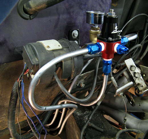
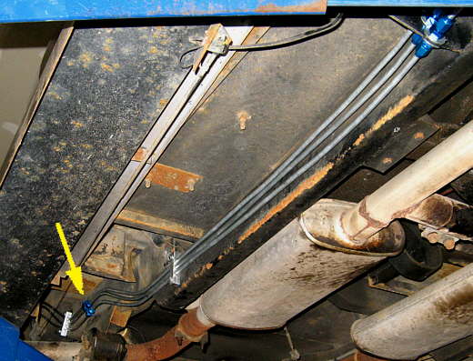
I bent lines for the regulator going back towards the tank/pump. The bottom is the return and the two side lines are the supply lines. All of these lines are 3/8 inch steel and the 2 supply lines are in anticipation of the possible fuel needs of the blown motor later.
............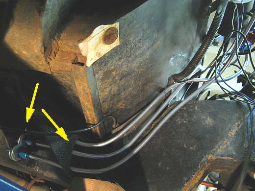
The lines went down through a hole I cut in the cab support that came off of the main frame rails (right arrow). The left arrows point to bulkhead fittings that I put in holes in the rear part of the cab support.
............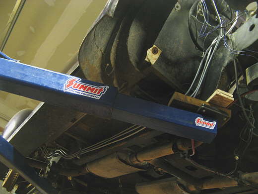
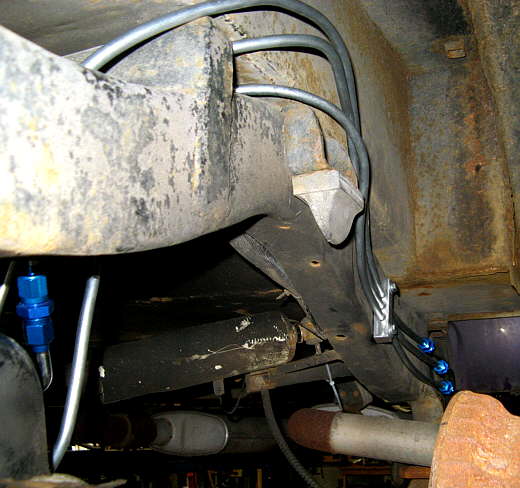
The bulkhead fittings are hidden by the arm on the lift. Form there back the lines run along side of the frame.
............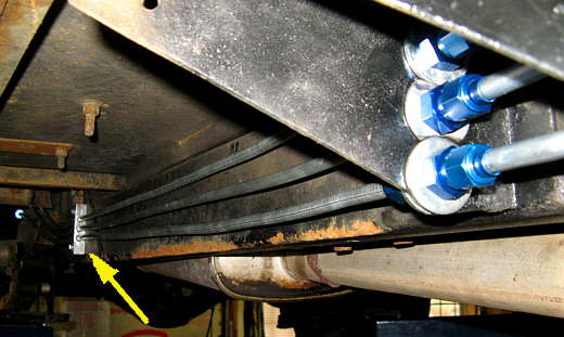
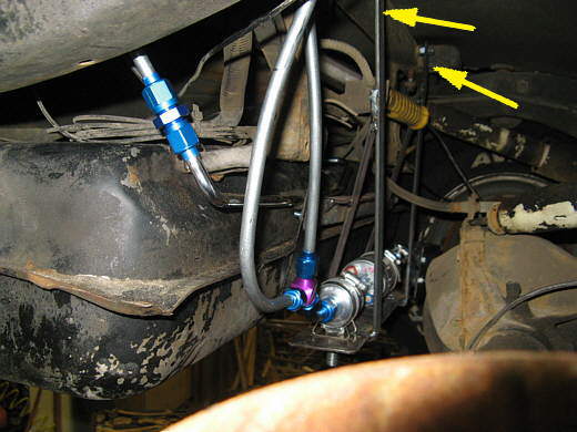
Here is a better view of the bulkhead fittings and the arrow points to one of the clamp blocks I had made.
............
Back where the frame kicks up there are 3 AN connectors, one for each line. So the lines are all in 3 parts. One from the frame down to the bulkhead fitting. Another from there back to the connectors (arrow) and the last section of lines from those fittings back to the tank and pump.
............
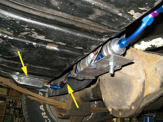
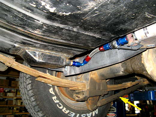
Here you can see the bottom supply line and how it goes over the frame at the back and down to a fitting (blue left side of picture) that connects it to what was the supply line coming form the tank sending unit. That line is now the return line. The two supply lines go over the frame in the same location.
............
Here you can see the return line and the two supply lines that connect to a "Y" just after the pump/filter. The arrows point to where the pump/filter bracket attaches to a frame cross-member. Later when the motor is blown if this pump doesn't deliver enough fuel I'll ditch the "Y" and add a second pump and filters and hook them to the other fitting on the tank sump and run a pump on each of the 3/8 inch supply lines that run from here forward.
............
The only flex line (right arrow) goes from the sump (left arrow) to the pre-filter and then the pump.
............
A close up of that area. The arrow points to the Cal-tracs I run. I like them.
............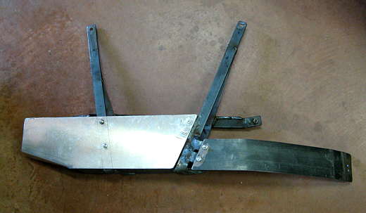
I made an aluminum and steel shield to protect the pump and filters from road debris.
............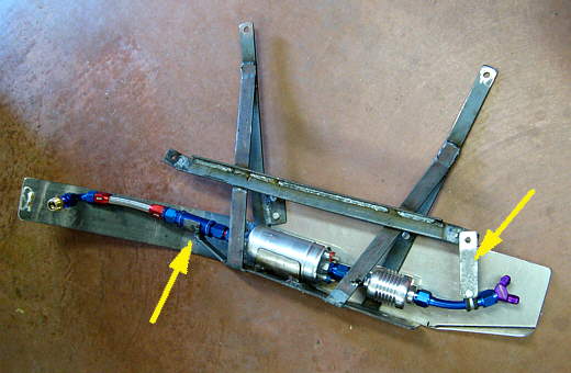
Here you can see I added a support (left arrow) for the pre-filter (not shown is a hose clamp that holds it to the support). Also I added a support for the short section of aluminum line right before the "Y" (right arrow).
............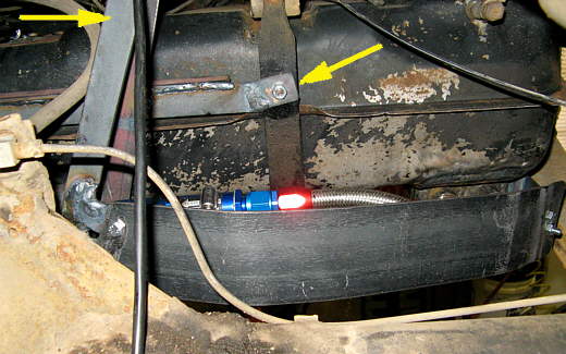
The arrows point to the locations of attachment for the pump/filter bracket assembly.
............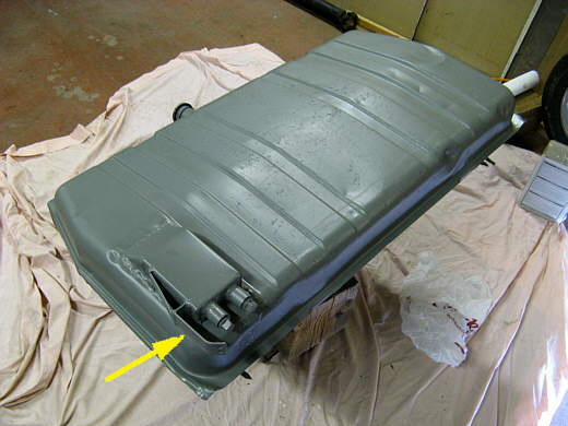
The arrow points to a bracket I welded to the sump that holds one end of a rock shield. I spent an afternoon using a tank restore kit from Eastwood that reconditioned the inside of the tank with a number of rinses followed by a white coating. I also cleaned the outside and shot it with PPG's DP-40 paint that is very corrosion resistant.
............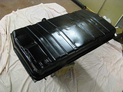
I followed that up with a top coat of black.
............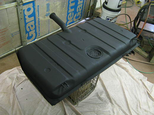
The previous 2 pictures showed the tank upside down. Here it is right side up. I also installed a new sending unit that had a 3/8 inch stainless supply line that I made into the return line.
The fuel system took a lot more time than I envisioned.